
Litre Meter Flowmeters Application Engineered
Litre Meter was founded in 1975 and is a very well recognised and established flowmetering company. All the flowmeters are relatively simple in their primary element design and are extremely reliable. The keynote of our company is excellence in engineering, we are exceptionally flexible and can produce application engineered flowmeters to meet specific needs.
Chemical Injection with Viscous Fluids
The VFF meter is ideal for chemical injection measurement. The fluids are dosed at relatively low flowrates and they are generally viscous in nature. The positive displacement principle of metering provides high accuracy for these difficult measurement conditions. Typical applications are: Scale inhibitor, Corrosion inhibitor, De- emulsifier, Oxygen Scavenger, Pour Point Depressant and Wax inhibitor.
VFF Rotary Meter
• The positive displacement principle offers measurement where turbine type meters will not operate. For example, a scale inhibitor of 90 cSt viscosity with a flow range of as little as 0.01 l/hr. The meter maintains metering accuracy for the varying viscosity of such a fluid with temperature changes.
• Chemically resistant materials of construction.
• Standard designs from 50 bar to 1,380 bar (20,000psi) and 4,000 bar (60,000 psi.) if required
Helical Screw Flowmeter
• Positive displacement meter - flowrange to 350 l/min.
• Unaffected by any line size change at flowmeter connections.
• Standard pressure ratings to 1,034 bar - higher ratings are available.
Hydraulic Line Monitoring for Well Control Valves & Leak Detection
Flowrates for this application are generally low requiring a suitable capacity flowmeter. A small size VFF Rotary Meter is ideal for this requirement and its Positive Displacement measurement principle provides major advantages for low flow service. VFF and Helical Screw flowmeters have wide rangeability and measure very low flows, which meet the requirements for leak detection service.
VFF Rotary Meter
• Allows 'footprinting' of valve actuator movement and confirms opening/closing operation. The VFF Meter provides superior accuracy and
• Better rangeability than ordinary turbine type meters, which are normally over-sized for the application
• Leak detection - from as little as 0.3 ml/min for common hydraulic fluids
• High viscosity fluids are measured from 0.1 ml/min
• Standard designs to 1,380 bar.
Helical Screw Flowmeter
• Leak detection but with high flowrate capability
Pelton Wheel Flowmeters LM and MM Series
• LM flowmeters offer low flow rate and wide rangeability from 0.004 l/min to 33 l/min for low viscosity fluids
• MM series orifice/by-pass designs from MM12.5, 1/2" to MM50, 2" size for high flowrates
• Accurate and repeatable with wide metering range
• Chemically resistant materials of construction
• Standard designs from 40 bar to 2,068 bar (30,000 psi.) Body designs include high pressure screwed, Grayloc hub connections or wafer types for flange fitting. The use of welds is avoided for offshore oil and gas duty
• Sensor Intrinsically Safe BASEEFA certified EEx ia IIc T5
• Connections are screwed, flange fitting or hub connector types
Accurate Positive Displacement Meters
Hazardous Area Readouts + Output
Chemical injection metering - topsides
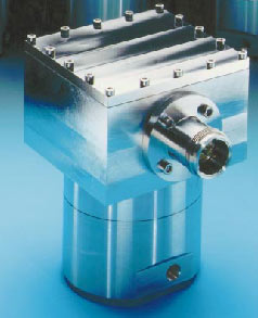
VFF Series for 520 bar to ASME B31.3 code shown
Chemical injection fluids are normally viscous and are therefore natural applications for the VFF meter. The flowrates are relatively low and the pressure is high compared to most general industrial applications. The VFF Rotary meter is the ideal measuring element for these service requirements. Long term stability of metering and reliability is assured by the basic simplicity of design and quality of production.
VFF Meter Design & Advantages
The heart of the VFF meter is a simple but precisely made, oscillating rotor that sits freely within the rotor chamber of the meter. It is manufactured in a variety of materials. The meter principle is of 'positive displacement'. The rotor is driven 'positively' by the flow, which passes through the flowmeter in 'discrete pockets' with minimum fluid 'slippage'. This gives inherently greater accuracy than is available from axial flow turbine type meters for a low flow of a fluid more viscous than water. Each meter provides a exceptionally wide flowrange and has excellent low flow metering capability.
Screwed & Flanged Fitting
Meters have threaded entries for either NPT or Medium Pressure 1,380 bar 20,000 psi tubing fittings or higher rated connections. Alternatively, they are available in flange fitting style for ANSI RF/RTJ. Even the higher pressure API 6BX (to 1380 bar) flanges or hub connectors may be specified. For installation, no straight pipe lengths are required and the line size can be varied directly at the flowmeter connections. For pressures over 20,000 psi we normally use Autoclave HP connections but we can manufacure to any standard required.
Meter Top Housing
The reed-switch sensor system is housed in a certified IP68 enclosure rated to 20m submersion and dust-tight. It provides a top or side mounting M20 gland connection for field cabling or alternatively for the mounting of a read-out instrument.
Intrinsically Safe or Flame Proof?
The VFF meter output is a 2-wire system providing a volt-free contact closure suitable for local instruments or transmission to a safe area. The output is considered 'simple apparatus'. The 2-wire connection to the safe area is isolated by a zener barrier or galvanic isolator device. If required a galvanic isolator is available which transposes the pulse output to a 4-20mA linear analogue 2-wire flowrate output signal. Alternatively, the meter output can be provided to an intrinsically safe local read-out or supplied as an Exd instrument in the hazardous area.
Approval to ASME B31.3
Lloyds Register provide accreditation of the VFF meter designs to the pressure vessel code ASME B31.3 as required. Compliance with this standard for flowmeters is a demand of many major companies in the Oil Industry. Whilst 90% of our designs fall within Standard Engineering Practice when assessed to the Pressure Equipment Directive we are PED certified to Module H and we can provide stress analysis, Fininte Element Analysis and assessment by Chartered Engineers to validate the designs backed up by testing facilities to 7,000 bar.
Well Valve Position Monitoring & Leakage Detection
Well control valve actuators are of small volume and are stroked slowly to avoid shocks. Confirmation of actuator displacement is of vital operational interest. The VFF Rotary meter completely achieves this objective. The positive displacement principle assures 1% accuracy in nearly all circumstances.
The VFF meter is symmetrical for both forward and return flows. A 1% accuracy is normally achieved with a single 'bi-directional' calibration factor including for other effects of flowrate and viscosity variation. Simply counting the meter output pulses gives verification that the actuator has opened or closed correctly. Continuous pulses indicate line or actuator leakage.
For the detection of leaks in well control lines the VFF Meter is ideal. It has a wide flow capability and typically offers 'leak detection' starting from 5 to 15 ml/min. For high viscosity fluids, leaks from 0.5 ml/min can be sensed. The meter is inherently robust, meters with brass rotors have been tested with repeated blowdown of 600 bar to atmospheric pressure without damage.
High flowrate meters are used for applications such as the detection of umbilical line losses.
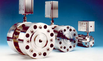
VFF Series for 520 bar & 690 bar and higher
With I.S. Rate and Total Readout Battery Powered
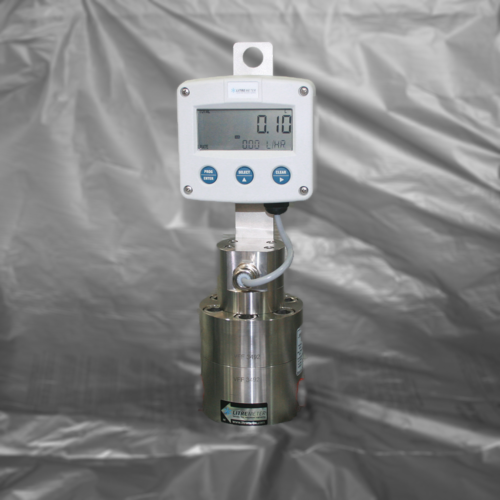
Self-Powered Readouts
The VFF meter is available as an intrinsically safe, battery powered stand- alone system, equipped with flowrate and totaliser indicator. Battery exchange is made without calibration memory loss.
Powered Instrument Systems
The battery powered stand-alone system can be equipped with a loop-powered 4-20mA flowrate output. When installed in this way the unit becomes powered by the loop with the battery function supporting the unit as a standby.
The battery powered stand-alone system with an intrinsically safe flowrate and totaliser indicator, can be equipped with a loop-powered 4-20mA flowrate output. The output is directly linear and proportional with flowrate.
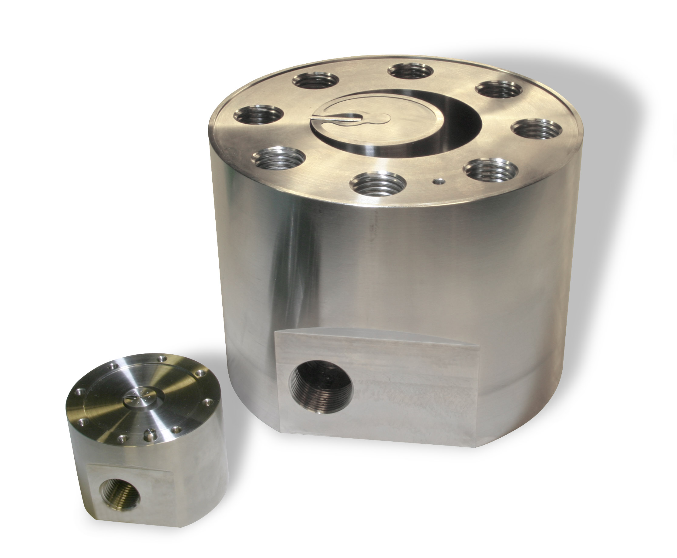
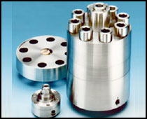
Modular VFF Meters with Pressure Balanced Chambers
For most meter constructions it is desirable to have an individual measurement module which Litre Meter designate Pressure Balanced Chamber or PBC. This allows a number of distinct advantages. The primary benefit is flow measurement independent of pressure. It allows Litre Meter to calibrate meters at 2 to 4 bar and know that they will be accurate at 2 to 4,000 bar. Secondly, materials of construction for the chamber can be optimally selected for best flow performance and can be different to the pressure vessel element that is optimised for pressure resistance. Thirdly, spare parting is significantly reduced in cost and volume. Fourthly, the smaller LF15, LF05 and LF03 have identical chamber sizes so can be changed at a later date when natural flow rates increase or decrease.
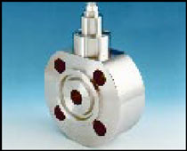
Pic 1) Wafer fitting for 1" flanges 2500lb RTJ
Pic 2) VFF Series 2,068 bar version with measuring module
VFF Series meter illustrated is for 690 bar service pressure
and up to 1000m submersion [1,035bar and 5,000m submersion designs have been manufactured]
The VFF Series Rotary Piston Meters are easily adapted for subsea chemical injection measurement. Their inherent reliability meets the low maintenance requirements of subsea service. Line pressures of 2,068 bar, (30,000 psi) can be currently met and higher pressures are possible. The maximum installation depth is only limited by the cabling connectors of the pressure-proof housing with its optional signal processing PCB. The PCB converts pulses from the sensor to a 4-20mA linear flowrate signal on a 2-wire output. The low power consumption allows the system to be loop-powered by the signal circuit as it needs less than 4mA.
Uniquely, two long life sensors are installed against a rare but possible sensor failure. The electronics automatically searches for a working one to use after a flow stoppage, loop disconnection or sensor problem.
The meter output is monitored directly by an ROV by plugging into the meter connector or via submarine cabling to a remote location. Using this vital information of actual flowrate the chemical injection flow control valves can be set correctly and in a cabled installation continuous on-line chemical injection monitoring is achieved.
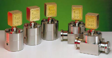
Helical Screw Meters
3" & 2" Wafer fitting type
for 690 bar API 6BX flanges to ASME B31.3
• Bi-directional metering of valve actuator hydraulic lines
• Leak detection for umbilicals - wide range allows both large flows and very low leakage rates to be measured
• Chemical injection metering of high flowrates
• Pressures to 1,034 bar. Intrinsically Safe and/or Flameproof.
The positive displacement, high pressure Helical Screw Flowmeter is superior to axial flow turbine meters for the measurement of viscous fluids. It is ideal for the precision measurement of fuels, hydraulic fluids and chemical injection.
The meters are extensively used for the metering of fuels in marine environments. They accept fluid viscosity change and retain very high measurement accuracy. They are extremely robust and reliable.
For off-shore umbilical lines, flowrates from 0.1 to 350 l/min are available. Each meter offers a wide flowrate range allowing the detection and metering of leakage flows.
Typical applications of chemical injections are: MEG (mono-ethylene glycol), PAO (poly-alphaolefin) and DEG (di-ethylene glycol) for chemical injection to gas lines.
The Meters have been used for permanent installations and temporary test purposes for the 'foot-printing' of valve actuator movement.
Low Viscosity Fluid Meters - Wide Rangeability
Pelton Wheel Flowmeters – available for high pressures
• Design Pressure 1034 barg / 50°C •
Lower pressure rating types are also available
Litre Meter Ltd was incorporated in 1975 to manufacture Pelton Wheel Flowmeters patented by its founder. Original meters are still in service illustrating their inherent reliability and long life. The principles of operation of the LM and MM Series for flowrates 0.010 to 500 l/min are shown.
Performance and Design
The Pelton Wheel Flowmeter is ideal for low-viscosity fluids such as wash water, methanol, biocide solutions etc. The meter offers very wide rangeability and also the ability to measure low flows. Body designs are adaptable and are produced for specified flowrate ranges and maximum service pressure requirements. Designs are available from 10 to 2068 bar+ in screwed, hub connection or wafer styles for flange fitting as appropriate. For maximum security, welds are avoided in our meter designs.
Pelton Wheel Turbine Ring Assembly
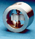
The turbine rotor is based on a highly efficient 'Pelton Wheel' design. The flow into the Pelton wheel is directed 'offset' to one side of the wheel. The flow travels with the rotation of the wheel through 180° imparting maximum drive. This principle also applies to the orifice/bypass MM Series. In addition, features such as low friction bearings and a 'no-drag' rotor motion sensing system result in a meter offering a wide dynamic flow range with linear output.
Lloyd's Register have accredited a special version where the Maximum Allowable Working Pressure is 2020 bar (29,290 psi) and certified for -20 to +50°C service. The sensor design testing was to ASME VIII Division 1: 1998 Subsection UG-101(m) at 10,345 barg (150,000 psi).
The flowmeter includes a KEMA certified EEx ia IIc T5 pre-amplifier electronics in a IP68 rated naval brass or 316 stainless enclosure. A high resolution, current sinking, pulse output is provided, which is ideal for long cable runs.
Viscosity Effects
Viscosity affects all turbine type meters where any non-linearity characteristic present is magnified and lowest flowrate measurement capability is lost due to viscous drag upon the rotor blades. For these reasons turbine-type meters are not generally selected for chemical injection service as these fluids such as scale inhibitor, corrosion inhibitor etc are mostly viscous. For such applications our alternative positive displacement meters should be used to achieve high accuracy measurement.
Sensor/ Transmitter to ASME/KEMA Approvals
High Pressure Intrinsically Safe Sensor System
• For Pelton Wheel, Helical Screw & VFF Flowmeters
• No magnetic 'drag' is imposed on the rotor
• Highest pressure rating systems tested to 11,400 barg, 165,300 psi (Pressure limited only by test jig leakage) Lloyd's Register witnessed
• Sensor housing and pick-up all 316 Stainless Steel – Liquid seal retained for field change of pick-up cartridge
Certification of Design
Many purchasers seek approval of flowmeters to the code ASME B31.3 for both Quality Assurance and Insurance purposes. We can meet this requirement for the manufacture of our flowmeters. For Pelton Wheel and VFF Meters the highest pressure design comprises of a body with a bolted-on cap which resembles a blank flange. The sensor system is attached to the meter cap and includes an in-service replaceable pickup or reed-switch. For Helical Screw meters the sensor system is attached directly to the meter body.
The Sensor Concept & Operating Pressure
The sensor outer shell is fixed to the flowmeter and has a field-replaceable internal pick-up. For the highest pressure version, the outer sensor shell is domed to form a pressure-resisting 'window' between the pick-up and the meter rotor. As a rigorous method of appraisal, Lloyds Register have verified the sensor design via ASME VIII Division 1: 1998 Subsection UG-101(m) burst-testing procedures. Many Lloyd's Register witnessed tests were performed with various materials and no samples failed. For the highest pressure design and using a cross- referenced but uncalibrated solid state sensor a 11,400 barg, 165,300 psi witnessed test was carried out, limited only by test jig leakage. This reconciles to a design pressure of 2,280 barg, 33,000 psi at 20 °C using a safety factor of five times. Minor deformation occurred at 11,400 barg noting that the objective of the test was to crush and burst it.
Later tests for ASME B31.3 appraisal were limited by the necessity of using a test gauge with traceable calibration. The maximum traceable pressure was 10,345 barg, 150,000 psi. Taking a safety factor of five times a Maximum Allowable Working Pressure of 2,020 bar, 29,290 psi at 50°C was certified based on actual material properties with traceable test pressure.
The exact features of the sensor dome as tested are incorporated in our high pressure sensor system. This ensures that the certified Maximum Allowable Working Pressures in Lloyd's Register plan appraisals can be used for production sensor assemblies.
I.S. Transmitter Assembly - Isolated Protection
and IP68 Rated Enclosure
• I.S. encapsulated transmitter electronics with secure 3 mA
• Seawater-resistant Naval brass BS2870 CZ112 or 316 Stainless Steel Enclosure
• Transmitter pre-amplifier in enclosure with 'O'-ring seal IP68 to 20m submersion
• Quick Release Assembly with Adjustable Orientation
• IP68 Integral Terminations Enclosure with M20 or M25 gland entry
IP68 Seawater-resistant Naval Brass or 316 Stainless Steel Transmitter Enclosure
The IP68 rated enclosure has two compartments each with an O-ring sealed lid. One houses the Intrinsically Safe encapsulated transmitter pre-amplifier electronics. This is easily removable and can be exchanged in service. The second compartment is a terminations enclosure with screw terminals and gland entry.
The O-ring seals are re- usable assuring that the full submersion protection can be maintained in usage.
The enclosure is orientation adjustable and with quick-release for easy sensor maintenance.
Flowmeter Selection and Principles
Meter Selection
The operating principles of the VFF and Helical Screw flowmeters are of positive displacement type where the flow is divided into discrete 'pockets' There is little slippage past the rotating elements and the fluid is therefore 'positively' metered with high accuracy.
Alternatively 'Inferential ' turbine flowmeters, infer the flow by the rotor being 'spun' as fluid passes through the meter and provide less inherent accuracy. For chemical injection applications involving low flow rates and hydraulic lines where the fluid can be static and cold, the fluid viscosity can be high and a positive displacement meter would be the preferred principle. The Pelton Wheel Flowmeter would be selected for such applications as wash water and other low viscosity fluids such as methanol.
VFF Series Meters
The basic design of our VFF meters is very well established and appears in the British Standard BS7405: 1991 section 3.3 which reviews recognised meter types. The flow causes a rotor to move within a measuring chamber. This movement is sensed, giving an output representing an increment of volume flow. Typically repeatability is better than 0.25% and a system accuracy of 0.5% can be obtained.
The rotor is basically a disc shape with an annular groove on its underside capable of holding and transporting flow from the chamber inlet to the outlet. Some fluid is also transported in a cavity formed between the rotor outside wall and the chamber wall. A centre 'peg' under the rotor is constrained to run in a circular groove in the body. A web in the body is engaged with a slot in the rotor and this modifies the rotation to that of an oscillation as flow passes. It is this oscillation that produces the compart- mentation of the fluid into positively displaced 'pockets'. The rotor top has a magnet encapsulated in 316 stainless steel (or titanium) directly above the 'peg' on the underside and so this also has a circular path which allows it to engage and disengage a reed-switch sensor located in the top cap above. A volt-free contact closure output signal is given for each oscillation representing a volume increment. The fluid is transported in a 'positive' manner at all times.
| VFF |
| Litre Meter has developed a flowmeter capable of operating at 4,000 bar (60,000 psi) and at a flow rate of 0.099cc per minute. The instrument has been produced for the American natural gas distribution network to help prevent compressor station failure. |
| Litre Meter has designed a pressure balance chamber for its VFF rotary piston flowmeter to enable it to operate at extreme pressure and at low-flow rates. The instrument has been developed to measure and verify the flow of mineral oil that lubricates machinery used to pressurise natural gas at compressor stations. |
| Natural gas is pumped at high pressure throughout the US via an interstate pipeline. To ensure that the gas remains pressurised it is compressed at compressor stations, which are located at 40 to 100 mile intervals along pipelines.
The machinery used to compress the gas is subjected to enormous strains as a result of the high pressure environment - conditions where metals can deform plastically. Reliable and continual operation of the equipment, however, is critical. If it fails, the supply of gas to many homes will stop and the cost of repair can easily run to $1 million. |
|
To keep the machinery operating reliably a constant flow of mineral oil is pumped through the equipment at a low flow rate of between 0.099 and 4.788 cc/min (0.06 and 0.282 l/hr) and at a pressure of 4,000 bar (60,000psi). This is to ensure that it reaches every capillary. |
| Litre Meter's flowmeter has been designed to continually measure the flow rate of mineral oil at the inlet feed. This measurement is used to verify that the correct amount of lubricant is being passed through the machinery. Litre Meter's flowmeter is capable of operating accurately and reliable in these conditions. The pressure balance chamber acts as a barrier, protecting the internal measurement components of the instrument from the high pressure conditions, preventing them from expanding and contracting under the immense pressure. By separating out the two meter functions - measurement and pressure containment - Litre Meter are able to optimise the materials of construction. Coupling this facility with a sensitive sensor and robust magnet makes high pressure measurement - with no loss in acuracy due to materials movement - a reality. |
| "Developing the technology to measure flow rates at the pressures involved in this application has been a tremendous feat," said Charles Wemyss, engineering director at Litre Meter. "Through developing our pressure balance chamber we are now able to offer our clients the capability of measuring low flow rates at extreme pressures."yd |
 |
Helical Screw Flowmeters
The Helical Screw Flowmeter has rotor scrolls which accept and release continuous flow. While the flow is being transported through the centre portion of the meter, it is trapped by the 'flights' of the scrolls, these form positive displacement 'pockets'. The meter inherently provides a high resolution pulse output from a many toothed polewheel on the end of one of the scrolls. The polewheel is sensed by the KEM or Litre Meter high pressure sensor and Intrinsically Safe transmitter electronics which provides a pulse or analogue output. The meter materials of construction are compatible with MEG and mineral or synthetic hydrocarbon hydraulic line fluids. The meter is ideal for fuel oils and has been widely used in the marine industry.
Pelton Wheel Flowmeters
The Litre Meter Pelton Wheel flowmeters employ a single size straight bladed rotor manufactured in chemically resistant PFA and having bearing balls of either tungsten carbide or sapphire. The rotor bearing balls run in hemispherical sapphire bearing cups forming two 'floating' low friction precision bearings. Ferrites sealed in the PFA rotor are sensed by a pick-up coil in the Litre Meter high pressure sensor and Intrinsically Safe transmitter system. The flow path for the LM series meters is shown where all of the flow travels with the Pelton Wheel and exits from the flowmeter. The meter provides a high resolution 3mA square wave pulse output.
LM Series meters are specifically designed for low flows (for example the LM24 size flowrange is 0.03 to 4.3 l/min) and have a wide turndown ratio of up to 280:1. For the MM Series an identical Pelton Wheel ring assembly is located in a by-pass chamber. The rotor movement is directly proportional to total flow through the flowmeter. This gives a wide rangeability, typically 50:1 for the MM orifice/by-pass meter.